Hydraulic Cylinder Basics

Introduction
Custom hydraulic cylinders (hydraulic rams, hydraulic actuators) come in all shapes and sizes, in various forms of construction, all suited to different applications.
At first glance, hydraulic cylinders appear very straightforward but, like many things in life, the devil is in the detail. Here we aim to broadly cover the key elements that require consideration when designing or selecting a cylinder solution for your equipment.
We will also attempt to decipher the terms used to describe hydraulic cylinder elements, clarifying some of the jargon used in different parts of the world and industrial sectors.
Linear Motion
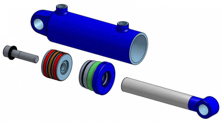
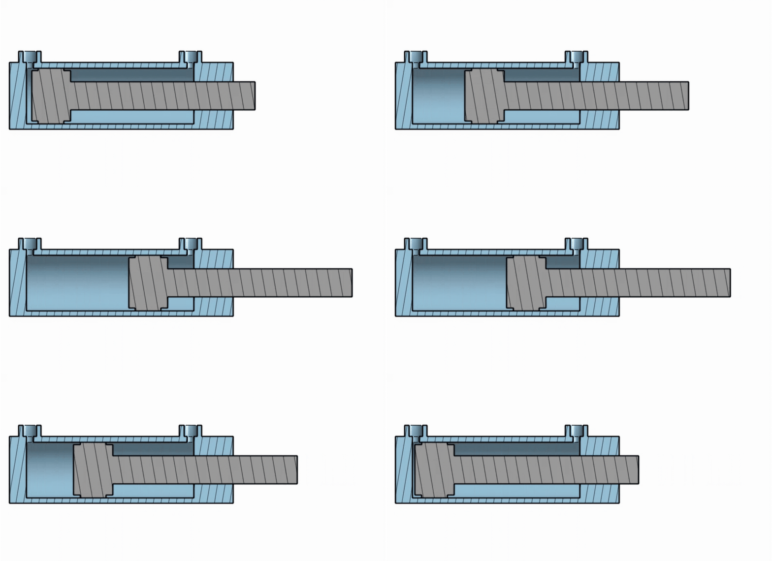
A hydraulic cylinder uses high-pressure fluid (oil) to convert pressure into and motion/force. The Rod Assembly moves relative to the Tube Assembly driven by the fluid pressure contained in the Tube Assembly.

The motion is guided by a pair of linear bearing surfaces that support the piston/rod in the tube bore and the rod in the tube head. Many forms of bearing system are commonly used in cylinder construction, depending on the technical and economic needs of the application. Factors to consider include:
- Operating speed
- Side Loading
- Life Expectancy
- Maintenance requirements
- Cost of Manufacture
Pressure Containment
The high pressures used to generate the linear motion must be safely contained inside the cylinder tube and connected to the hydraulic system providing the energy input. This pressure is contained by the joints used in the cylinder tube construction. Pressure joints may be:
- Statically sealed
- Permanent e.g. welded joints
- Mechanically assembled
- Dynamically sealed
- Allowing sliding motion while continuing to contain the fluid pressure.
Mounting
Now that we have force and motion happening, we must consider how to use this in a machine application. This involves mounting the cylinder in a way that enables the desired movement and ensures reliable operation of the machine.
As mentioned previously, hydraulic cylinders are linear devices and will benefit from ensuring that the loads they they exert, and/or loaded with, act along the central axis of the cylinder bore. Careful consideration of the mounting and integration of the cylinders is vital to minimising undue wear and tear.
There are many common forms of cylinder mounting:
- Fixed clevis - allowing flexing in one plane. Most common and inexpensive.
- Male
- Female
- Plain
- Bushed
- Trunnion - allowing flexing in one plane, while offerring greater flexibility in closed centre distance.
- Spherical - allowing self alignment of the cylinder with it's mounting/action points.
- Flange - fixing the cylinder body relative to the machine frame.
When designing the mounting arrangement for a hydraulic cylinder the required motion of the machine and it's strength, symmetry and stiffness are important considerations.
Hydraulic Connection and Control
Until connected to a hydraulic system, the cylinder cannot function. Manual or electrically controlled valves direct oil pressue to the cylinder through pipes and hoses to create the desired movement and force. The design of the hydraulic system is critical to the effective and safe operation of the machine. Integrated load control and pressure relief valves can be important to protect the machine, it's user(s) and the environment from uncontroled movement or overload.
With the integration of linear position transducers, closed loop motion control can provide increased functionallity and control.
If you would like to learn more about a custom cylinder design for your machine application contact info@victor.co.nz
